Before we build our real robot we need to prototype (try out) some of the ideas for parts and strategies we will use in the real bot. Fortunately we have an existing robot that has a chassis pretty much perfect for trying out ideas.
The test robot has a 3d-printed chassis with grid holes on its front and lid that make it easy to attach test parts for various projects. It has 4 brushed motors driving Mecanum (omnidirectional) wheels, and is controlled from a ps4 controller (using Approximate Engineering’s software drivers on a Raspberry Pi Zero). Though not relevant to this particular test, it has a TFT display and a NeoPixel ring on its back end that provide a lot of operational information on commands and battery / system status.
Because we want to eventually try to make this work autonomously, we also included mounts for some sensors we want to try out. They’re shown in the video, but we left them out of the OpenSCAD design code we show below, because they are really fodder (pun intended…) for another story. And because we haven’t actually done anything with them yet.
So, on to the good news. It works. Mostly. A little bit. Sort of… The prototype did its job and pointed out the flaws in our concept. As a proof-of-concept, it was a success. We’ll fix the oops-es and carry on with this as the strategy.
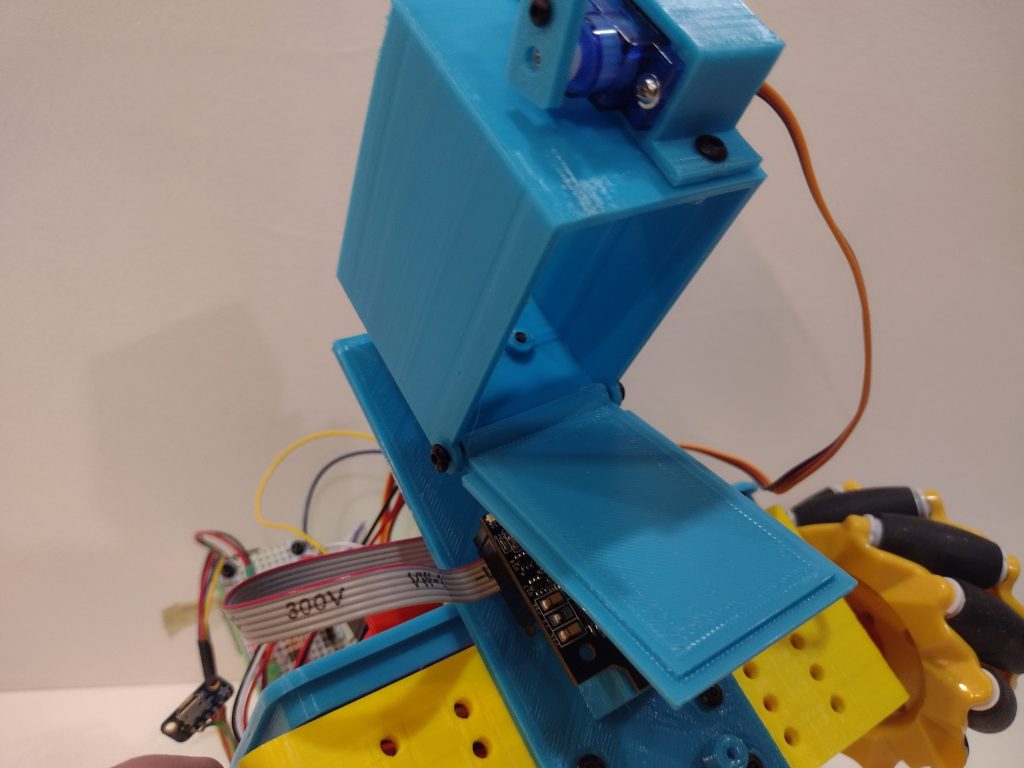
For sure the driver (oops, me…) had some issues with accuracy and driving skills. The major design flaws became much more obvious in the physical reality than they were in the imagination. You probably noticed that we put a camera on the front of the mounting bracket, in anticipation of later using that to help find and accurately position the robot in front of a trough. You probably also noticed that the trap door totally blinds it when it opens. Oops ! Might need to rethink that… You’ll also notice that the hopper needs to be mounted a little higher so its opened door wouldn’t bump into the food trough on the next approach. But, fundamentally, it does drop food.
On the “plus side”, the unanticipated interference between the camera and the trapdoor made the trapdoor turn into a pretty nice ramp that helps to spread out the feed. Even though we plan to relocate the camera (and probably replace it with a Pi Zero with a tiny spycam on OpenCV), we’ll probably put in a “stop” to duplicate that ramp effect.
Our plan is to ultimately have 3 of these hoppers arranged horizontally on the mounting bracket, one for each food trough. And each hopper will be tall enough to hold enough food to fill a single hopper to the required half-way point. The one shown here is “shorter” to reduce printing time since its only a prototype.
What it looks like / How it works
This is how the hopper door operates; the door itself is on a pivot at the back. Normally a small “catch” holds it closed. The catch is mounted on an SG-90 micro servo which can be activated to release the door
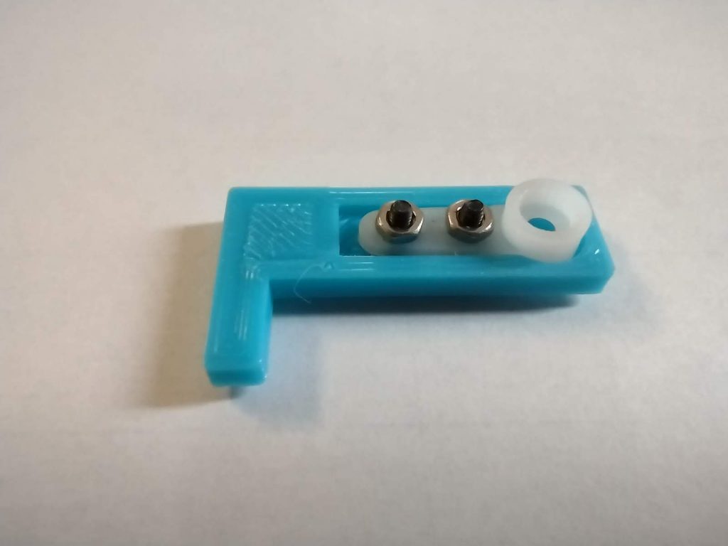
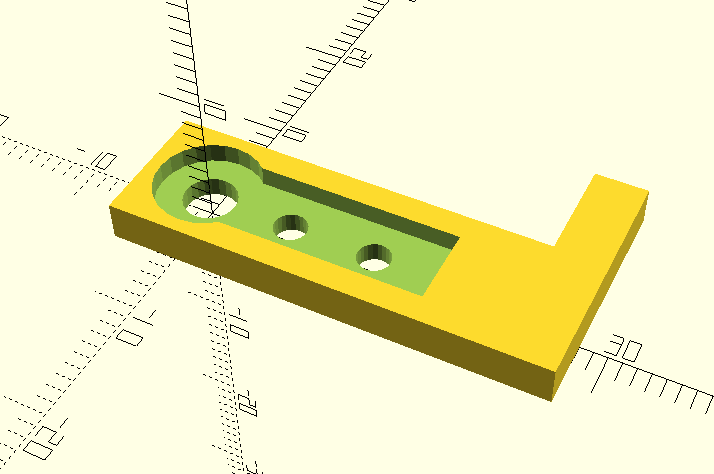
The photos below show details of the catch mechanism. Note that the catch is printed with a small pocket into which a standard servo horn is bolted with M2 bolts (its too hard to print the tiny teeth that actually mount to the servo itself).
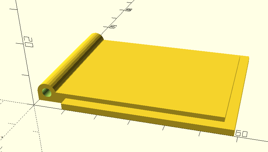
The trapdoor has a lip to make a clean seal for the “feed”. It rotates on pivots that are actually M3 bolts screwed into a tubular sleeve on the back edge of the trapdoor. Note that the centerline of the pivot should be inline (vertically) with the joint line between the hopper and the trapdoor to avoid binding or interference crashes.
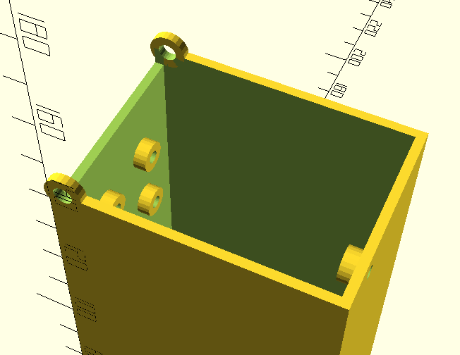
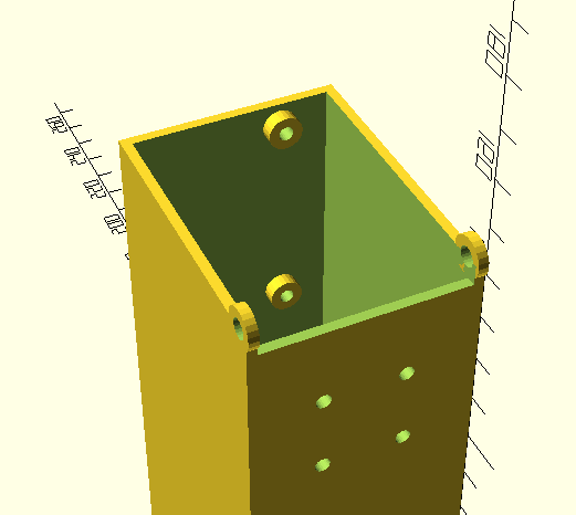
The bottom of the bin has holes for M3 screws that act as pivots; these holes are 4mm dia so that the screws turn freely in them (and the screws are not “fully tightened” when installed). As noted above, these pivot holes are vertically inline with the joint line. Also note that the “back” of the bin has a vertical clearance gap to allow room for the axle sleeve.
The “front” of the bin has mounting holes that the servo mount box bolts into, the back of the box has mounting holes that are used to attach the bin to the mounting bracket. Note that in the pictures below, the bin is shown “upside down” because it is oriented in the way that prints best (with no supports).
The CAD Design
The OpenSCAD code that generates the hopper parts is as shown below.
// note part should be "bin" or "door", "servo", or "catch"
draw_part("catch");

bin_l = 55;         // interior length of bin (x)
bin_w = 40;         // interior width of bin (y)
body_wall_thickness = 2.0;
door_clearance_gap = 1.0;       // clearance gap between door lip and inside of bin box

axle_ring_dia = 8;              // ring that surrounds axle hole in bin
axle_offset_x = 3;              // axle distance from back wall
shaft_vertical_clearance = 4;   // height of gap in bin back wall to clear axle shaft
shaft_horizontal_clearance = 9; // gap in door bottom lip to clear axle shaft

grid_spacing = 16;              // for mounting grid (mount trough to robot)
grid_height = 20;               // height of first grid row above bin bottom
grid_mount_tube_dia = 7;        // to help self-tap screws grab
grid_mount_tube_len = 5;        // to help self-tap screws grab

oversize_multiplier = 1.25;
volume_needed = 100 * 100 * 25 * oversize_multiplier;
// bin_h = 52;       // used only for testing, normally use volume-calculated from below
bin_h = volume_needed / (bin_l * bin_w);

bin_outer_l = bin_l + (2*body_wall_thickness);
bin_outer_w = bin_w + (2*body_wall_thickness);

// standard part dimensions
M3_selftap_dia = 3;
M3_throughhole_dia = 4;
M2_selftap_dia = 2;
M2_throughhole_dia = 2.5;
M25_selftap_dia = 2.5;

module draw_part(part) {
    if (part == "bin") {
        draw_bin();
    }
    if (part == "door") {
        draw_door();
    }
    if (part == "servo") {
        draw_servo_mount();
    }

    if (part == "catch") {
        draw_door_catch();
    }
}

// note that the bin is generated "upside down" to facilitate support-less 3d printing
module draw_bin() {
    $fn = 24;
    difference() {
        union() {
            difference() {
                // make outside of basic box
                cube([ bin_outer_l, bin_outer_w, bin_h ]);
                // remove inside of box
                translate([ body_wall_thickness, body_wall_thickness, -0.1 ])
                    cube([ bin_l, bin_w, bin_h + 0.2 ]);
            }

            // add rings that surround axle bolts
            translate([ axle_offset_x, 0, bin_h ])
                rotate([ -90, 0, 0 ])
                cylinder ( d=axle_ring_dia, h=body_wall_thickness);
            translate([ axle_offset_x, (bin_outer_w - body_wall_thickness), bin_h ])
                rotate([ -90, 0, 0 ])
                cylinder ( d=axle_ring_dia, h=body_wall_thickness);

            // make mounting grid tubes (to thicken wall so self-tap screws grab)
            translate([ 0, (bin_outer_w/2) - (grid_spacing/2), bin_h - grid_height ])
                rotate([ 0, 90, 0 ])
                cylinder ( d=grid_mount_tube_dia, h=grid_mount_tube_len );
            translate([ 0, (bin_outer_w/2) + (grid_spacing/2), bin_h - grid_height ])
                rotate([ 0, 90, 0 ])
                cylinder ( d=grid_mount_tube_dia, h=grid_mount_tube_len );
            translate([ 0, (bin_outer_w/2) - (grid_spacing/2), bin_h - grid_height - grid_spacing ])
                rotate([ 0, 90, 0 ])
                cylinder ( d=grid_mount_tube_dia, h=grid_mount_tube_len );
            translate([ 0, (bin_outer_w/2) + (grid_spacing/2), bin_h - grid_height - grid_spacing ])
                rotate([ 0, 90, 0 ])
                cylinder ( d=grid_mount_tube_dia, h=grid_mount_tube_len );

            // make mounting tubes for servo mount
            translate([ (bin_outer_l - grid_mount_tube_len), 12, bin_h - 5 ])
                rotate([ 0, 90, 0 ])
                cylinder ( d=grid_mount_tube_dia, h=grid_mount_tube_len );
            translate([ (bin_outer_l - grid_mount_tube_len), 12, bin_h - 5 - 42 ])
                rotate([ 0, 90, 0 ])
                cylinder ( d=grid_mount_tube_dia, h=grid_mount_tube_len );
        }

        // make vertical room for axle sheath
        translate([ -0.1, body_wall_thickness, (bin_h - shaft_vertical_clearance) ])
            cube([ body_wall_thickness + 0.2, bin_w, shaft_vertical_clearance + 0.1 ]);

        // make throughholes for axle bolts
        translate([ axle_offset_x, -1, bin_h ])
            rotate([ -90, 0, 0 ])
            cylinder ( d=M3_throughhole_dia, h=56);

        // make mounting grid (holes for selftap)
        translate([ -0.1, (bin_outer_w/2) - (grid_spacing/2), bin_h - grid_height ])
            rotate([ 0, 90, 0 ])
            cylinder ( d=M3_selftap_dia, h=grid_mount_tube_len + 0.2 );
        translate([ -0.1, (bin_outer_w/2) + (grid_spacing/2), bin_h - grid_height ])
            rotate([ 0, 90, 0 ])
            cylinder ( d=M3_selftap_dia, h=grid_mount_tube_len + 0.2 );

        translate([ -0.1, (bin_outer_w/2) - (grid_spacing/2), bin_h - grid_height - grid_spacing ])
            rotate([ 0, 90, 0 ])
            cylinder ( d=M3_selftap_dia, h=grid_mount_tube_len + 0.2 );
        translate([ -0.1, (bin_outer_w/2) + (grid_spacing/2), bin_h - grid_height - grid_spacing ])
            rotate([ 0, 90, 0 ])
            cylinder ( d=M3_selftap_dia, h=grid_mount_tube_len + 0.2 );

        // make mounting holes for servo mount
        translate([ (bin_outer_l - (grid_mount_tube_len + 0.1)), 12, bin_h - 5 ])
            rotate([ 0, 90, 0 ])
            cylinder ( d=M3_selftap_dia, h=grid_mount_tube_len + 0.2 );
        translate([ (bin_outer_l - (grid_mount_tube_len + 0.1)), 12, bin_h - 5 - 42 ])
            rotate([ 0, 90, 0 ])
            cylinder ( d=M3_selftap_dia, h=grid_mount_tube_len + 0.2 );
    }

    echo("hopper height = ", bin_h);
}

module draw_door() {
    $fn = 24;
    wall_and_gap = body_wall_thickness + door_clearance_gap;

    difference() {
        union() {
            // thick part of door (box bottom)
            // note it is the raised part that should fit "inside" the bin box
            translate([ 0, wall_and_gap, 0 ])
                cube([ (bin_outer_l - wall_and_gap), (bin_w - (2*door_clearance_gap)), (body_wall_thickness + 1.5) ]);

            // outer "lip" for door (thin part of door)
            // (should match outside dim of bin, less shaft horizontal clearance gap)
            translate([ shaft_horizontal_clearance, 0, 0 ])
                cube([ (bin_outer_l - shaft_horizontal_clearance), bin_outer_w, body_wall_thickness ]);

            translate([ wall_and_gap, wall_and_gap, wall_and_gap ])
                rotate([ -90, 0, 0 ])
                cylinder ( r=wall_and_gap, h=(bin_w - (2*door_clearance_gap)));
        }
        translate([ wall_and_gap, 0, wall_and_gap ])
            rotate([ -90, 0, 0 ])
            cylinder ( d=M3_selftap_dia, h=bin_outer_w);
    }
}

module draw_servo_mount() {
    $fn = 24;
    screw_separaton = 28;

    pocket_length = 24;
    pocket_width = 13;
    mountbox_width = 18;
    mountbox_length = 35;
    mountbox_depth = 19;

    mountbox_tab_l = 50;
    mountbox_tab_screw_sep = 42;

    difference() {
        translate([ -mountbox_length/2, -mountbox_width/2, 0])
            cube([ mountbox_length, mountbox_width, mountbox_depth ]);

        translate([ -((pocket_length/2) + 0.1), -pocket_width/2, -0.1 ])
            cube([ pocket_length+0.2, pocket_width, mountbox_depth+0.2 ]);

        translate([ -screw_separaton/2, 0, -0.1 ])
            cylinder( d=M2_selftap_dia, h=mountbox_depth+0.2 );
        translate([ screw_separaton/2, 0, -0.1 ])
            cylinder( d=M2_selftap_dia, h=mountbox_depth+0.2 );
    }

    translate([ 0, -mountbox_width/2, 0 ]) difference() {
        translate([ -mountbox_tab_l/2, 0, 0 ])
            cube([ mountbox_tab_l, 2, mountbox_depth ]);
        translate([ -mountbox_tab_screw_sep/2, -0.1, mountbox_depth/2 ])
            rotate([ -90, 0, 0 ])
            cylinder( d=M3_throughhole_dia, h=2.2);
        translate([ mountbox_tab_screw_sep/2, -0.1, mountbox_depth/2 ])
            rotate([ -90, 0, 0 ])
            cylinder( d=M3_throughhole_dia, h=2.2);
    }
}

module draw_door_catch() {
    $fn = 24;
    arm_w = 10;
    arm_thick = 3;
    servo_axle_x = 5;
    horn_shaft_dia = 8;
    pocket_bottom_z = 1.5;
    pocket_axle_to_end_x = 18;
    pocket_width = 6;
    catch_from_axel = 24;
    catch_width = 4;
    catch_length = 18;
    arm_l = servo_axle_x + catch_from_axel + catch_width;
    hole1_x = 6.5;
    hole2_x = 13.0;

    difference() {
        union() {
            translate([ -servo_axle_x, -arm_w/2, 0 ])
                cube([ arm_l, arm_w, arm_thick ]);
            translate([ catch_from_axel, -arm_w/2, 0 ])
                cube([ catch_width, catch_length, arm_thick ]);
        }
        translate([ 0, 0, -0.1 ])
            cylinder( d=M3_throughhole_dia, h=arm_thick + 0.2 );
        translate([ 0, 0, pocket_bottom_z ])
            cylinder( d=horn_shaft_dia, h=arm_thick );
        translate([ 0, -pocket_width/2, pocket_bottom_z])
            cube([ pocket_axle_to_end_x, pocket_width, arm_thick ]);
        translate([ hole1_x, 0, -0.1 ])
            cylinder( d=M2_throughhole_dia, h=arm_thick + 0.2);
        translate([ hole2_x, 0, -0.1 ])
            cylinder( d=M2_throughhole_dia, h=arm_thick + 0.2);
    }
}
Note that the code is heavily parameterized. The most likely parameters that would be changed to support a new robot are bin_l, bin_w, and oversize_multiplier. These control the length (front-to-back) and width (side-to-side) of the bin.
The height of the bin is calculated in the code to hold a sufficient volume of “food” to fill the 100 x 100 x 50mm bin half-way. Note that the oversize-multiplier parameter allows you to allow room for a bit extra to allow for spillage. In this example the parameter is set to 1.25 which gives 25% extra.
The “standard part dimensions” screw diameter parameters and the door_clearance_gap parameter can be used to tune your design to match the actual extrusion profiles of your 3d printer.
To run this code, simply paste it into the OpenSCAD editor. You can change the parameter in line 2 to select which part will be generated when you render the design. There are 4 possibilities: “bin”, “door”, “catch”, and “servo” (which generates the clamp that mounts the SG90 servo).
The Python Code
The servo is driven by a PWM signal generated on the Raspberry Pi Zero controller. This code uses the pigpio library to generate PWM signals that are jitter-free.
The setup for the library and hardware is as follows:
import RPi.GPIO as GPIO
import pigpio
#
# note it is important to "sudo pigpiod" at bootup to allow this to work...
#
# verified that it works with all 3 servos, even though documentation
# seems to suggest that there is only one PWM generator in pi.
# probably only needs one generator to work even with multiple pins
# https://ben.akrin.com/?p=9158
#
# the pin numbering is per gpio numbers.
# tested with GPIO.24, GPIO.25, and GPIO.9 simultaneously
#
servo = 24
pwm = pigpio.pi()
pwm.set_mode(servo, pigpio.OUTPUT)
pwm.set_PWM_frequency( servo, 50 )
The code used to open and close the trapdoor latch is as follows (if you build one, the actual constants (600 and 1500), which represent the pulse width, will probably be different, based on your angular placement of the arm on the servo motor shaft):
if joystick.presses.l1:
    print("pressed L1 servo 600 LATCH TRAPDOOR")
    pwm.set_servo_pulsewidth ( servo, 600 )

if joystick.presses.l2:
    print("pressed L2 servo 1500 OPEN TRAPDOOR")
    pwm.set_servo_pulsewidth ( servo, 1500 )
Wrap-Up
So we are encouraged to know that our initial prototype shows that the idea will work. We will need to make some hardware tweaks to fix the OOPS-es, and we’ll need to try it out with a full-height bin just to make sure there’s no surprises there, but we feel like this is indeed the approach we will use for this challenge.