In a 3-team field of Beginner teams… And we had a LOT of fun doing it, and learned a LOT. Hopefully we’ll get the chance to try this again in 2023. It was great to have the chance to watch the creative ways that everyone else approached the same challenges we did.
This shows a combination status display / stopwatch panel that provides visual feedback on the progress of our challenge runs on the videos. The display is built from (2) 32×64 LED matrix displays, giving a total field of 32×128 pixels. It uses an Adafruit MatrixPortal to drive the panel and to connect to an MQTT broker over the network to receive commands.
While the unit was built specifically for the PiWars challenges, it could be easily used for any competitive event that would benefit from a display of status messages and event timing.
The panel is 130×500 mm in size, using the 4mm pitch display panels from Adafruit, but 3mm pitch or 6mm pitch panels could be substituted to achieve different physical sizes at this resolution, or the field “width” or “height” can be extended by adding additional panels, with minimal software changes.
Software and complete documentation including message protocols is available on Don’s Tech Stuff site.
Those who watched our challenge videos will remember that there was a bug in the stopwatch code that caused it to “run slow”. The bug is fixed in the posted code. It was a careless error, born of rushing to get this ready for filming, but its a great reminder that (1) rushing is rarely a good idea, and (2) code reviews ARE ALWAYS a good idea.
So, we don’t actually “pluck” the apples. We sort of bash them instead. Lacks a bit in finesse or elegance, but it’s simple, and pretty effective.
Basically, we have a “knocker” at the height of each branch. The knockers have fingers positioned at the location where the apple stems are on the branch (pretty handy that these trees have such consistently placed apples…).
The apples are attached to the tree with small magnets. When the robot approaches the tree, the fingers restrain the apples so they don’t “pivot” upwards too much, and the back knocker panels push them off the tree.
They fall into a “scoop” container at the front of the robot, and at the end of the run the robot returns to the barn, raises the scoop and dumps the apples.
So after our earlier discovery that rice is indeed heavy, we re-thought our strategy for delivery. We now use 3 bins that rotate on a turntable. This way the mass is concentrated over the wheels instead of in front of the wheels.
Each bin is filled with enough rice to fill a bin half-way, plus 20%. Each bin has a servo-operated trap door at the bottom that allows the rice to be delivered all in one big “gush”. The turntable is driven by a small stepper motor, geared down by 4x so it can handle the necessary torque (did i mention that rice is heavy???).
We did it !!! BrattyPi was able to successfully feed the Hungry Cattle and pluck the Nature’s Bounty apple tree. We didn’t do quite as perfectly as we had initially hoped (and we didn’t play with any sheep), but we made a very respectable effort, learned a lot, and had a LOT of fun doing it. Can’t wait for you all to see the videos in July.
We haven’t been very attentive to this blog in quite a while (life happens…), but we expect to start updating it to show technical documentation for the various parts of our project now that the pressure to “get it working” is past.
So this week on the Discord a lively conversation bounced around the subject of the weight of the Cattle Food that we need to transport for the Hungry Cattle challenge.
The Barn Rats team previously demonstrated a pretty successful dispenser that was able to fill a food trough to the required volume. But we had not really given any consideration or thought to the issue of what would happen if we had 3 of those dispensers hanging off the front of our robot.
Uh. That might have been a mistake…
Turns out that the short answer to the question is … we’re going to need to substantially rethink our design.
The dispenser works pretty well, as long as the robot is not trying to go anywhere. Driving it around however is a bit of a problem… Its way too front-heavy for our test chassis.
The chassis is about 180 mm square, with the dispensers sticking out about 100mm to the front of it. The robot body itself weighs 1300g. The front-mounted dispenser weighs in at about 400g empty, and 1000g when filled with 600g of dry rice, which is the amount it would take to fill 3 food troughs to 50%.
The robot has no trouble moving the mass around, even though this test chassis just uses tiny TT motors. Unfortunately backing up, or stopping from forward motion causes the whole thing to tip over…
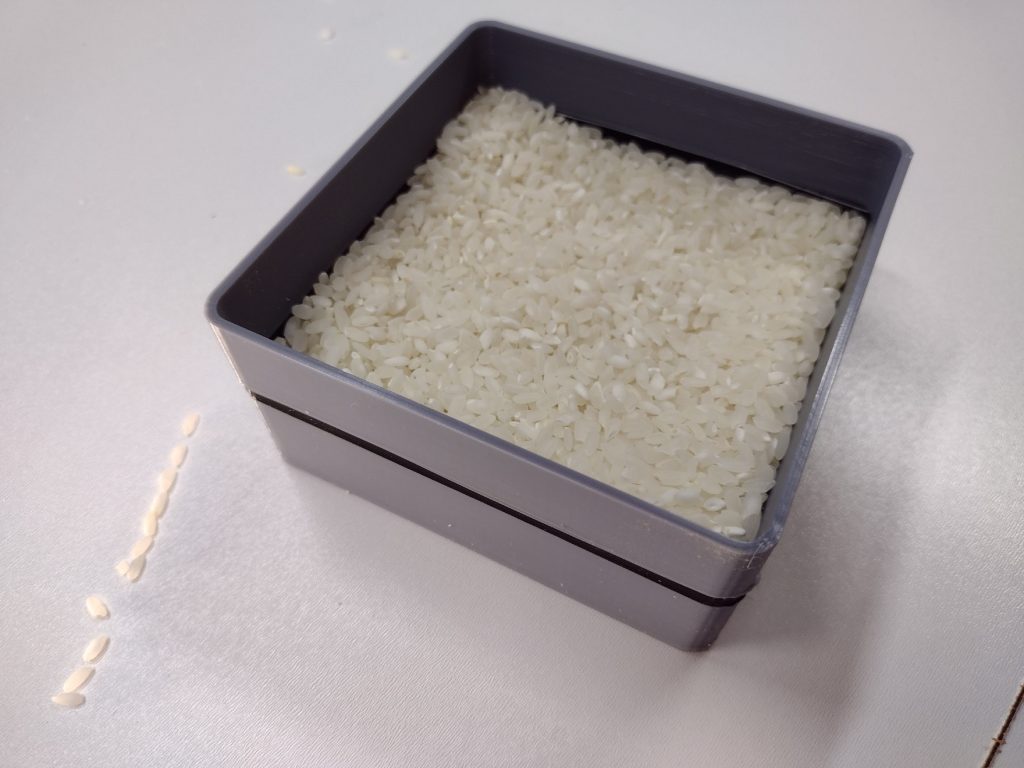
On the flip side (poor pun intended), it DOES do a pretty good job of dispensing the rice. Most of the rice actually makes it into the food trough. The central bin with the front-dropping trapdoor does a better job than the side bins which have side-facing trapdoors. But as you can see in the photo we do manage to get the bin up to just over half full (the black stripe starts at the 50% point (thanks for the idea @keegan).
So it looks like some redesign is in order. Thinking about moving the bins “back” so their mass is mostly between the robot wheels, then having a slide to aim the rice down towards the trough. Mom always used to say that “there are no fails in life, just opportunities to learn”…
The big lesson here is “pay attention to the mass of that rice”. It is probably not insignificant compared to the mass of your robot.
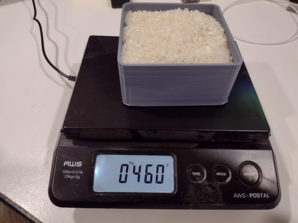
For those wondering about how much weight you’ll need to carry around in that Hungry Cattle challenge, here’s some background info.
This is using dry white rice. My empty trough is 76 grams, a full-ish one is 460 grams. So just under 400 grams of rice to fill one trough completely, or about 200g to fill one half-way.
So 3 troughs would be about 600g.
If you’re worried about weight, i wonder what an equivalent volume of Rice Crispies would weigh? Or if cows like Rice Krispies ??
@keegan had a great idea in today’s Discord (jan 9) — when you print your troughs, change color half-way up to make it easy to show that its half-full.
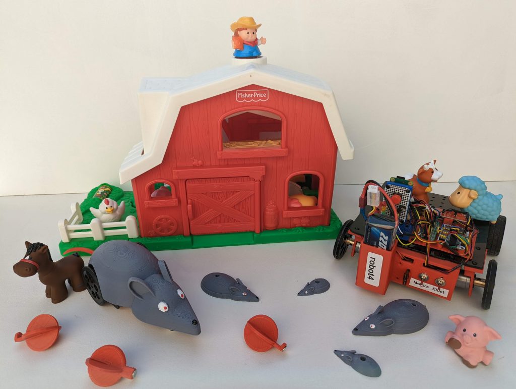
Hi — i’m little bRat, and i’ll be your guide this next couple months as we watch those tech guys teach my big brother bRattyPi some new tricks. I’m actually the smart one in the family, but big brother wants to believe he is. He thinks he’s a pretty cool dude, but me and all the sibs know he’s actually pretty square.
Me and all the brothers live in a barn that lives in a basement in the middle of Michigan, in the US of A. Its a pretty cool place, with lots of screens and technical gizmos. I don’t really understand a lot of that stuff, but big bro bRattyPi claims he does and that he’s itching to learn how to play with some of the new toys those tech guys are making. Frankly, i think its just fleas that have got him itching.
Anyhow, here’s a pic of me and the fam, just hangin’ out (that’s me – the biggest and handsomest rodent in the photo above; big bro bRattyPi is the guy dressed in yellow and blue; all together we’re the family of Barn Rats). You’ll be seeing a lot of us this next couple months as we all watch bRattyPi learn his stuff.
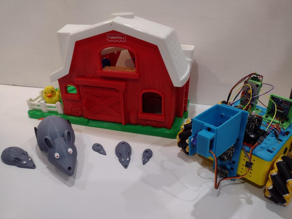
Before we build our real robot we need to prototype (try out) some of the ideas for parts and strategies we will use in the real bot. Fortunately we have an existing robot that has a chassis pretty much perfect for trying out ideas.
The test robot has a 3d-printed chassis with grid holes on its front and lid that make it easy to attach test parts for various projects. It has 4 brushed motors driving Mecanum (omnidirectional) wheels, and is controlled from a ps4 controller (using Approximate Engineering’s software drivers on a Raspberry Pi Zero). Though not relevant to this particular test, it has a TFT display and a NeoPixel ring on its back end that provide a lot of operational information on commands and battery / system status.
Because we want to eventually try to make this work autonomously, we also included mounts for some sensors we want to try out. They’re shown in the video, but we left them out of the OpenSCAD design code we show below, because they are really fodder (pun intended…) for another story. And because we haven’t actually done anything with them yet.
So, on to the good news. It works. Mostly. A little bit. Sort of… The prototype did its job and pointed out the flaws in our concept. As a proof-of-concept, it was a success. We’ll fix the oops-es and carry on with this as the strategy.
For sure the driver (oops, me…) had some issues with accuracy and driving skills. The major design flaws became much more obvious in the physical reality than they were in the imagination. You probably noticed that we put a camera on the front of the mounting bracket, in anticipation of later using that to help find and accurately position the robot in front of a trough. You probably also noticed that the trap door totally blinds it when it opens. Oops ! Might need to rethink that… You’ll also notice that the hopper needs to be mounted a little higher so its opened door wouldn’t bump into the food trough on the next approach. But, fundamentally, it does drop food.
On the “plus side”, the unanticipated interference between the camera and the trapdoor made the trapdoor turn into a pretty nice ramp that helps to spread out the feed. Even though we plan to relocate the camera (and probably replace it with a Pi Zero with a tiny spycam on OpenCV), we’ll probably put in a “stop” to duplicate that ramp effect.
Our plan is to ultimately have 3 of these hoppers arranged horizontally on the mounting bracket, one for each food trough. And each hopper will be tall enough to hold enough food to fill a single hopper to the required half-way point. The one shown here is “shorter” to reduce printing time since its only a prototype.
What it looks like / How it works
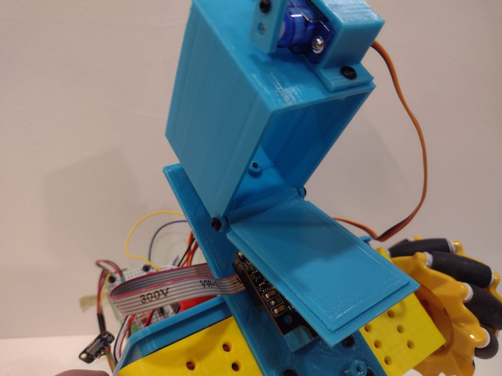
This is how the hopper door operates; the door itself is on a pivot at the back. Normally a small “catch” holds it closed. The catch is mounted on an SG-90 micro servo which can be activated to release the door
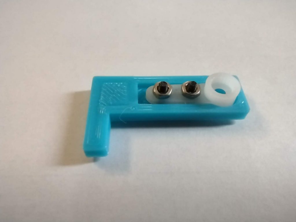
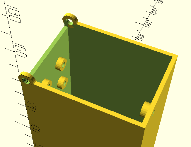
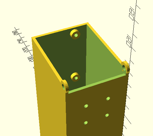
The photos below show details of the catch mechanism. Note that the catch is printed with a small pocket into which a standard servo horn is bolted with M2 bolts (its too hard to print the tiny teeth that actually mount to the servo itself).
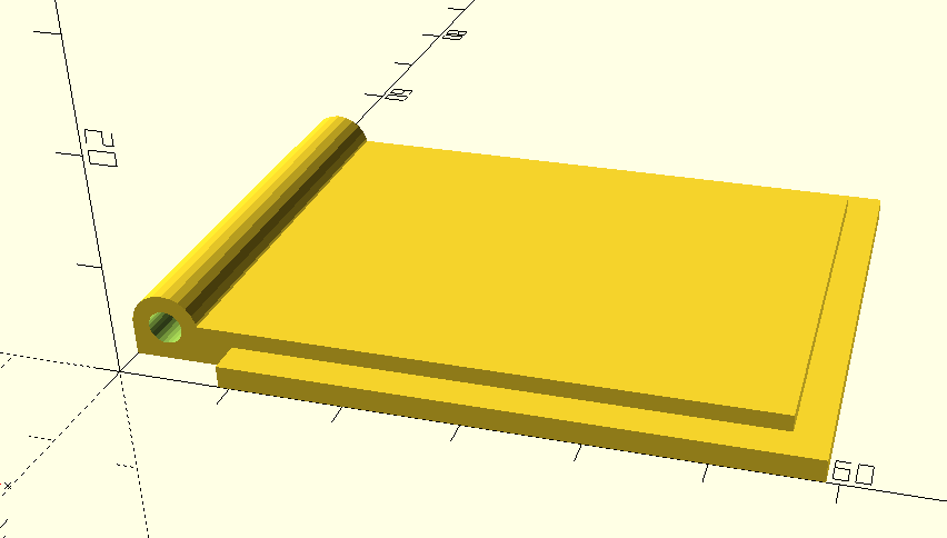
The trapdoor has a lip to make a clean seal for the “feed”. It rotates on pivots that are actually M3 bolts screwed into a tubular sleeve on the back edge of the trapdoor. Note that the centerline of the pivot should be inline (vertically) with the joint line between the hopper and the trapdoor to avoid binding or interference crashes.
The bottom of the bin has holes for M3 screws that act as pivots; these holes are 4mm dia so that the screws turn freely in them (and the screws are not “fully tightened” when installed). As noted above, these pivot holes are vertically inline with the joint line. Also note that the “back” of the bin has a vertical clearance gap to allow room for the axle sleeve.
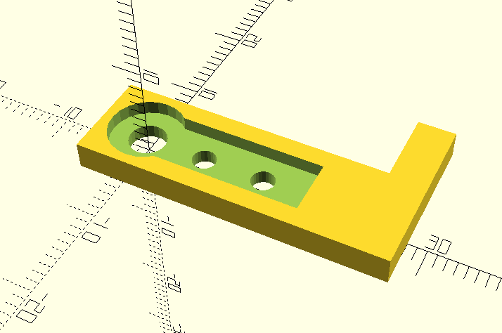
The “front” of the bin has mounting holes that the servo mount box bolts into, the back of the box has mounting holes that are used to attach the bin to the mounting bracket. Note that in the pictures below, the bin is shown “upside down” because it is oriented in the way that prints best (with no supports).
The CAD Design
The OpenSCAD code that generates the hopper parts is as shown below.
Note that the code is heavily parameterized. The most likely parameters that would be changed to support a new robot are bin_l, bin_w, and oversize_multiplier. These control the length (front-to-back) and width (side-to-side) of the bin.
The height of the bin is calculated in the code to hold a sufficient volume of “food” to fill the 100 x 100 x 50mm bin half-way. Note that the oversize-multiplier parameter allows you to allow room for a bit extra to allow for spillage. In this example the parameter is set to 1.25 which gives 25% extra.
The “standard part dimensions” screw diameter parameters and the door_clearance_gap parameter can be used to tune your design to match the actual extrusion profiles of your 3d printer.
To run this code, simply paste it into the OpenSCAD editor. You can change the parameter in line 2 to select which part will be generated when you render the design. There are 4 possibilities: “bin”, “door”, “catch”, and “servo” (which generates the clamp that mounts the SG90 servo).
The Python Code
The servo is driven by a PWM signal generated on the Raspberry Pi Zero controller. This code uses the pigpio library to generate PWM signals that are jitter-free.
The setup for the library and hardware is as follows:
import RPi.GPIO as GPIO
import pigpio
#
# note it is important to "sudo pigpiod" at bootup to allow this to work...
#
# verified that it works with all 3 servos, even though documentation
# seems to suggest that there is only one PWM generator in pi.
# probably only needs one generator to work even with multiple pins
# https://ben.akrin.com/?p=9158
#
# the pin numbering is per gpio numbers.
# tested with GPIO.24, GPIO.25, and GPIO.9 simultaneously
#
servo = 24
pwm = pigpio.pi()
pwm.set_mode(servo, pigpio.OUTPUT)
pwm.set_PWM_frequency( servo, 50 )
The code used to open and close the trapdoor latch is as follows (if you build one, the actual constants (600 and 1500), which represent the pulse width, will probably be different, based on your angular placement of the arm on the servo motor shaft):
if joystick.presses.l1:
    print("pressed L1 servo 600 LATCH TRAPDOOR")
    pwm.set_servo_pulsewidth ( servo, 600 )

if joystick.presses.l2:
    print("pressed L2 servo 1500 OPEN TRAPDOOR")
    pwm.set_servo_pulsewidth ( servo, 1500 )
Wrap-Up
So we are encouraged to know that our initial prototype shows that the idea will work. We will need to make some hardware tweaks to fix the OOPS-es, and we’ll need to try it out with a full-height bin just to make sure there’s no surprises there, but we feel like this is indeed the approach we will use for this challenge.
We Made It !!! The Barn Rats are officially entered in PiWars 2022. We’re excited to participate, to learn, and to become active members of the PiWars community.
The official “competing” Barn Rat is named bRattyPi and he will be introduced later in the season. His younger brother little bRatis excited to make your acquaintance and will be introduced here shortly.